![[IMAGE] Site Location](../img/case.gif)
|
Outline
ELSYCA CP-MASTER Simulation of a CP System for Buried TankELSYCA PLATINGMASTER Copper Plating of Non-uniformly Patterned Wafer Gold Wafer Plating Process in a Cupplater Decorative Cr plating process for a rack of wheels Bipolar Pulsed Simulation of a Cu Plating Process Cr Plating Process for a Rack of Shower Tap Parts Acid Zn Plating Process for a Brake CaliperDOWNLOAD Download Studies as pdf |
SIMULATION OF A CP SYSTEM FOR A BURIED TANKTitle: Simulation of a CP system for a buried tank influenced by a steel reinforced concrete foundation Soil Type: Wet sand Applied software tool: Elsyca CP-Master Industry: Oil & Gas industry Validity and Reliability: Excellent agreement between simulated and measured cathodic protection (CP) levels Goal of Simulations: Investigate the shielding effect of a plastic (PE) screen in order to improve the CP level of the buried tank surface Customer Benefits: Substantial time & cost savings in design and operating phase Description: The CP level of a buried tank (or pipe) can be influenced to a considerable extend by a neighbouring steel reinforced concrete foundation, if the latter is connected electrically to the CP system. Depending on geometrical parameters such as the distance between the tank and the foundation, far field potential, soil resistivity etc., the CP level of the tank can drop far below the minimum required value (e.g. 850 mV vs Cu-Cu sulphate reference electrode). A typical situation is plotted in figure 1, the tank being only a few meters away from the foundation. The CP levels over the tank surface as computed by Elsyca CP-Master are plotted for the side facing the far field in figure 2, and for the foundation side in figure 3. The CP level at the foundation side drops locally to about 600 mV (hence severely underprotected), whereas the far field side remains well protected. A plastic screen being positioned between the coated tank and the foundation has a clear and beneficial influence on the CP level of the tank surface facing the foundation (figure 5), improving local CP levels by about 200 mV. The far field side of the tank is still well protected (figure 4), with only a small improvement in CP levels compared to the situation without screens. Defining the configuration from figure 1 in the SolidWorks CAD environment takes only a couple of hours, with another 10 minutes to compute the CP level over the tank surface with Elsyca CP-Master. Redefining the screen (position, size) takes only a few minutes, hence the screen configuration can be optimized easily within half a day time. Also the definition and simulation of additional screens and/or anode beds would take only a few minutes. Figures: 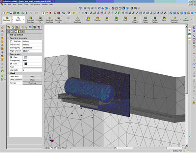
Figure 1: CP-Master user environment with surface mesh for tank, vertical screen and foundation 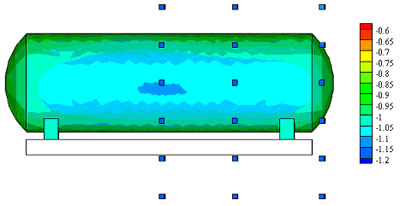
Figure 2: Protection level (vs Cu-Cu sulphate) for the far field side of the tank (small cubes represent possible reference electrode positions) no screen 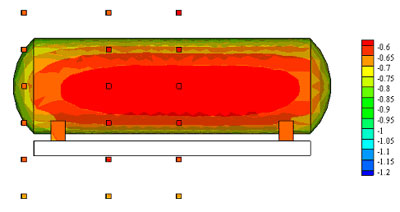
Figure 3: Protection level (vs Cu-Cu sulphate) for the foundation side of the tank (small cubes represent possible reference electrode positions) no screen 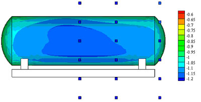
Figure 4: Protection level (vs Cu-Cu sulphate) for the far field side of the tank (small cubes represent possible reference electrode positions) - with screen 
Figure 5: Protection level (vs Cu-Cu sulphate) for the foundation side of the tank (small cubes represent possible reference electrode positions) - with screen |
Rose Consulting Engineers LimitedWe are an independent provider of computational fluid dynamic (CFD) flow modelling services to all manufacturing sectors and are the UKs only authorised reseller/partner of Elsyca electrochemical simulation software |
|
|
|
|
|
|
|
|