1. Introduction.
Our client operates an incinerator as part of an off-gas treatment facility at their chemical manufacturing site. During commissioning, the monitored emission levels were occasionally exceeding the Environment Agency operational limits. This had to be attended to immediately as failure to comply with emission limits risked plant closure. Since the gas treatment system was used for several process streams, closure of this facility would have had serious consequences for the client's business.
Two possible causes for the emissions were considered, namely breakthrough, that is the passage of unburned material from delivery lance to stack, or formation where unburned fuel, deposited in the heat exchanger, reacted to form undesirable products. Insufficient time-temperature exposure could result in either of these scenarios.
2. The Model
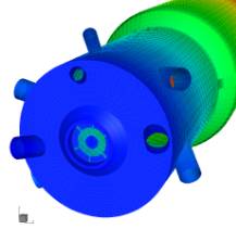
Rose Consulting modelled the combusting flow in this complex geometry considering two process fuel streams and the natural gas burner.
Figure 1: The complex geometry of central burner and fuel lances was modelled with a finite volume grid.
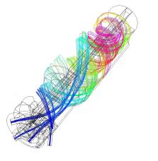
The model was used to test the fuel time-temperature residence requirement of 1000°C for two seconds. The results showed that although the required temperatures were achieved, some of the material was not experiencing the necessary residence time.
|
Figure 2: Traces from the delivery lances are coloured with time. Magenta is in excess of 2 seconds. Short circuiting is observed from three of the fuel lances.
Several retrofit options were considered such as building baffles or changing inlet flow distributions. These options were discussed with the client and tested with further models.
3. The Result
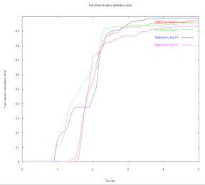
Cumulative residence time distributions (CRTD) were examined to see which option produced the steepest CRTD and therefore the best mixing.
Figure 3: Particles below an exit time are summed and the result plotted to the CRTD. The optimum condition is where all particles approach the hydraulic retention time of 2 seconds.
4. Conclusion
Our client now further understands their process and the effect of several retrofit options. This information is being used to effectively plan the plant upgrade during the next shutdown.
|
![[IMAGE] Site Location](../img/consulting.gif)